
In my last post, I described how I made a spark-gap transmitter and receiver. For the transmitter, I used a car's ignition coil to produce high voltage sparks, and for the receiver, I used a coherer to detect the transmissions. A coherer is a simple device - it consists of iron filings between two electrodes. Normally the filings have very high electrical resistance (tens of megaohms), but when the coherer detects electromagnetic waves, its resistance drops to about 10-20 ohms.
Back in the day, spark gap transmitters and coherers were widely used for wireless communication. One of the early pioneers in the field of wireless communication was Arthur "Artie" Moore. He has a very interesting story. As a teenager, he built a steam engine using water-wheel driven lathe, and entered the model in a competition. He received as his prize a book by Sir Oliver Lodge titled "Modern Views of Electricity" which sparked his interest in the world of wireless. He, along with his friend Richard Jenkins, began to experiment with the ideas presented in Lodge’s book. They successfully built their own spark-gap transmitter and coherer receiver and taught themselves Morse code. Artie built a little radio station in his attic, and he would stay there all night listening to signals emanating from ships traveling the coastal waters around Wales.
 |
| Artie Moore's radio shack |
In the early hours of 15 April, 1912, Artie received a faint Morse code signal on his coherer receiver:
"CQD Titanic 41.44N 50.24W."
CQD meant "come quickly distress." In its next message, the ship also used the newer SOS signal -
"CQD CQD SOS de MGY Position 41.44N 50.24W. Require immediate assistance. Come at once. We have struck an iceberg. Sinking."
Artie was copying the signals, hardly believing the words he was writing. The final transmission he received was - "Come as quickly as possible old man; our engine-room is filling up to the boilers."
The RMS Titanic was sinking in the North Atlantic with more than 2,000 passengers and crew, and Artie was receiving the oceanliner’s final distress calls almost 3,000 miles away on his homemade radio. Artie continued to copy the increasingly desperate messages until the Titanic went silent about two hours after the first distress call.
The news of the disaster had not reached UK at that time, and no one believed Artie when he said that the Titanic was sinking. They thought that the Titanic was unsinkable. It was only two days later when it was announced in the national press, people realized he had been right. The receiving of these signals is believed to be the only land-based reception of the Titanic’s last transmissions in the UK, possibly the world.
 |
| Titanic's wireless room replica |
The receiver
Getting back to our story, I built my own coherer in a vinyl tube with iron filings:
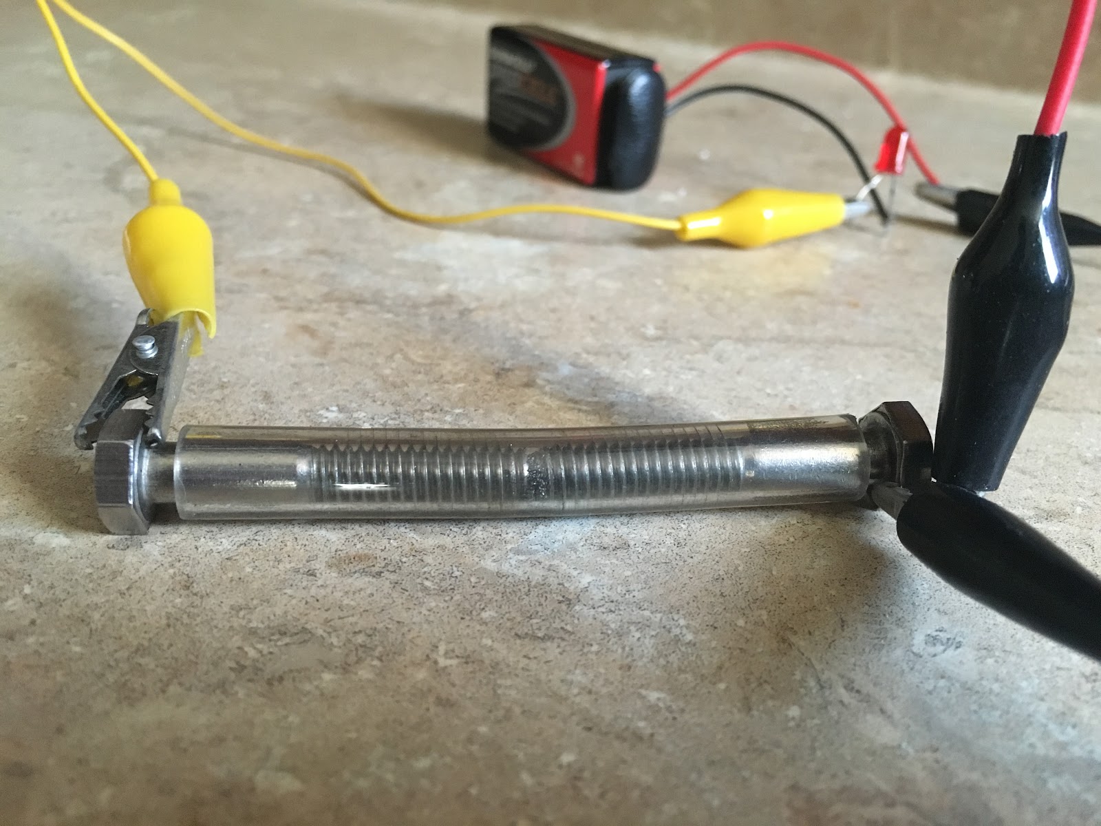 |
| Iron filings coherer |
A problem with the coherer is that once it gets activated, a physical tap is needed to reset it so that it can receive signals again. The system that resets a coherer is called a decoherer. I built a decoherer mechanism using a doorbell. Whenever the coherer gets triggered, it switches on a doorbell, and the bell's hammer hits the coherer and resets it.
 |
| Decoherer mechanism |
The coherer cannot drive the bell directly, because it draws a lot of current. So, I use a transistor to amplify the signal from the coherer, and the transistor drives a small relay. The relay switches on the doorbell.
 |
| Receiver circuit |
I connected the receiver to a Beaglebone to decode the received signals. I use an optoisolator to connect the output of the receiver to the Beaglebone. The optoisolator is an extra safety precaution to ensure that the Beaglebone is protected from any unwanted transients in the receiver circuit. I also added a flyback diode on the doorbell’s electromagnet to protect the optoisolator. Lastly, you’ll notice that there’s a brown capacitor in the doorbell to reduce sparking on the contacts. This is not necessary, but it should extend the life of the contacts.
The transmitter
In my previous post, I used a 555 timer-based ignition coil driver in my transmitter. I kept blowing the MOSFETs in that circuit from the inductive kickback produced by the ignition coil. So, I built the driver using a relay instead. The relay has been wired as an oscillator so that it turns the ignition coil on and off very quickly. This electromechanical driver is simpler and a lot more reliable. There's an automotive ballast resistor in the circuit to reduce the current on the primary side. I also salvaged a capacitor (aka condenser) from a car and put it across the relay's poles to reduce arcing on the relay. It's a standard ignition coil capacitor, and it filters out the inductive kickback coming from the coil.
 |
| Transmitter circuit (ignition coil driver) |
 |
| Spark-gap transmitter |
It is important to know that operating spark-transmitters is illegal because they create lots of RF interference. This transmitter can be operated without an antenna to keep the signals from going too far.
Connecting the coherer to a Beaglebone and decoding Morse code!
I connected my coherer to a Beaglebone, and wrote some Python code to decode the messages it receives back to text (receiver circuit above explains the circuit connections). You can find my code here.
Here is a video of the system automatically decoding Morse code signals!
A strange phenomenon
While I was testing my program with the coherer, a loose wire in the receiver's circuit got disconnected, and the decoherer (bell) stopped working. To my surprise, I noticed that my program continued to receive the signals I was sending, and it was even correctly decoding them back to text! How could the system work if the decoherer wasn't even resetting the coherer? I disconnected the Beaglebone from the receiver, and just kept the interface circuit (the optoisolator) connected to it. Now, the receiver wasn't even connected to the Beaglebone. I started sending signals with my transmitter, and to my surprise, the same thing happened again. The Beaglebone was receiving the signals and decoding them! It took me a moment to realize that I had accidentally built a crystal radio (aka cat's-whisker radio). The LED inside the optoisolator was receiving the RF from the spark transmissions, and lighting up. The photo-transistor darlington pair in the optoisolator was amplifying this weak signal, and this was changing the state of the Beaglebone's GPIO pin. How interesting!
This "unintentionally made" crystal radio receiver doesn't have a very good range (only a couple of feet), but I’m sure it could be improved upon to make a more sensitive receiver (and without any mechanical parts).
I hope you enjoyed this project as much as I did. I'd love to hear your thoughts and comments.
EDIT: There is a better explanation for the strange behavior of the 4N33 optoisolator. I received this comment from Perry Harrington on Hackaday:
"If you look at the 4N33, the base of the darlington pair is brought out to a pin. This pin is left necessarily floating, but a darlington pair has typically a ~10,000 gain, so even a small current on this floating base will result in the pair amplifying a current. The bias transistor will have 3.3ma of current flow through it when fully triggered. My experience with 3.3v logic is that it has a ~2.7v input trigger threshold, so you’re looking at about 2.7ma flowing through the darlington to trigger the BBB. If my math is right, it would take about 270na of stray current to trigger the darlington of the optoisolator without a current being present on the LED.
You could probably replicate the results with a TIP120 wired up the same, with the base pin floating. If you are using a breadboard, the grid tie it is connected to would act as an antenna."