I have been working on a project at the Mobile Robotics Lab of IISc (Indian Institute of Science), Bangalore, in which I have to design a vision based obstacle avoidance algorithm for robots. What does that mean? Well, I basically have to design a robot that uses nothing but a small camera to identify obstacles in its path. Since image processing and computer vision stuff is usually quite CPU intensive, it is difficult to implement this code on a small robot. Small microcontrollers can't handle that stuff. So, the solution I came up with involves a wireless camera that transmits video to a nearby "big" computer. This big computer runs all the dirty computer vision codes, identifies the obstacles, and then somehow tells the robot how to avoid them. This is where wireless communication comes in.
To create a wireless link, you could rip the guts of a cheap RC car and use its transmitter and receiver to control your robot. That's one technique. I did something similar a few years ago . This time, I wanted to do things a little more elegantly, without destroying an RC car. I found this really inexpensive RF transmitter/receiver pair at a local electronics shop in Bangalore:


They cost only 200 INR (about 4 USD)...both transmitter and receiver. What a steal!
You can also find these online at Sparkfun:
Transmitter - http://www.sparkfun.com/products/8945
Receiver - http://www.sparkfun.com/products/8948
They cost a little more on Sparkfun, but they're still inexpensive. The ones on Sparkfun operate at 315 Mhz, but the ones I have, operate at 434 Mhz (like this one). I don't think that would make any difference in how you connect them.
To use these cheap RF modules, you could either connect them directly to your microcontroller/computer, or connect them with the help of parallel - serial encoder/decoder ICs.
I used the HT12E (parallel to serial encoder) and the HT12D (serial to parallel decoder) ICs. The HT12E is a 12 bit parallel to serial encoder. Of those 12 bits, 8 bits are the address code, and the remaining 4 bits are data. To send a signal, the address bits on the transmitter and receiver should be the same. It's like a password. You can use a single RF transmitter to control different RF receivers (at the same frequency) by configuring the address bits appropriately. All receivers would have to be set to different addresses. With 8 bits, you can create a total of 256 combinations.
Here's what the serial data coming out of the encoder looks like, in an oscilloscope:
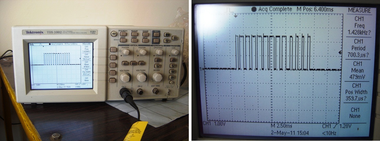
If you look closely, you'll notice that there are 13 peaks (instead of 12). I'm not sure what the first bit is for. (Probably a parity bit?) The 8 bits coming after the first bit make the address, and the last four make the data being sent. You connect your microcontroller's (or computer's) parallel output to the 4 input channels on the encoder. With 4 bits, you can create 16 unique commands. That is enough for my purpose.
For more on how to use these ICs with the Tx/Rx, check out this excellent article - http://www.botskool.com/tutorials/electronics/general-electronics/building-rf-remote-control
Here's a flowchart of my system:

I've connected an Arduino to my computer which acts as an interface between the encoder and my computer. Here's the Arduino that I'm using:

It's a ModernDevice BBB Arduino Clone that I received from my friend Tom Boyd. I've been hooked to it ever since I got it! You should definitely get an Arduino if you don't already have one. It's the perfect tool for the programmer who enjoys playing with electronics. And it's also very easy and fun to use!
Tom has some excellent tutorials on electronics and programming on his website that keeps inspiring me! Check out some of his awesome Arduino projects - http://sheepdogguidecools.com/arduino/ahttoc.htm.
The robot I am using is a Microbric Viper robot that I received from Microbric a few years ago. The Microbric Viper comes with an IR module which can be used to communicate with a computer wirelessly. Although I've used it in the past, it's kind of difficult to set up because infrared communication requires line-of-sight. Moreover, the range is quite limited.

I'm not going to get into the details of connecting the encoders/decoders with the RF modules because it is already covered in detail in the article I mentioned earlier. I am however, going to share some difficulties I have faced in using these RF modules.
When I was testing the receiver on a breadboard, I was powering it with an AC to DC adapter. The voltage was fine, but the decoder did not work at all. Why? When I was debugging the circuit with an oscilloscope, I realized that the signal at the encoder side was fine, with 13 distinct peaks. However, when I checked the data at the receiver side, I realized that there was some sort of noise, and the peaks were not distinct. The address bits were too close together and sometimes even merging together. Since the address bits on the decoder side did not match with this noisy data, it rejected it. I figured that this noise could be caused by radio interference noise from the AC to DC adapter. So, I removed it and powered each of them (Tx and Rx) with two AA batteries.
The other thing I noticed is that if you connect the third pin of the RF receiver (which is either marked as "Data" or "CE") to the data-IN pin of the decoder , the circuit won't work. Leave it unconnected.
I'm using a 1/4 wave monopole antenna (6.8 inches) with the RF modules. It's just a single core wire. The range I get is amazing. I think I get about 100-120 ft (through walls), and 1000+ ft outside (line-of-sight)! More than enough for my purpose. When I test it outside, it just keeps working no matter how far I go. So, I don't really know its limit yet!
The Arduino communicates with my computer through a USB to Serial cable. If I want to make the robot move forward, I would send the character '1' to the Arduino. It would recognize this as a command and forward it to the transmitter. I can send four commands to the Arduino - '1', '2', '3' and '4'. On receiving these characters, it sets the appropriate data bits on the encoder and transmits the signal.
Arduino code:
On Windows, I use a C# application to send these commands to the Arduino. On Linux, I just use the terminal. My Arduino shows up as /dev/ttyUSB0. To send the command '1', I write...
echo -n "1" > /dev/ttyUSB0
This makes the robot move forward. For a more interactive session, you can use the screen command:
screen /dev/ttyUSB0 9600
More on this here - http://www.arduino.cc/playground/Interfacing/LinuxTTY
And finally, the thing you were probably waiting for...a video! -
I hope you enjoyed this post. My next step would be to put a wireless camera on this robot and test my obstacle avoidance algorithm. Wish me luck.
I hope the information I've shared helps you build your own radio controlled electronic devices and robots!
So what did you think? I'd love to hear your feedback in the section below.
Ashish