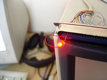
Wednesday, November 29, 2006

Camera Panning Using Parallel Port Controlled Floppy Drive

The set-up:


Webcam view:


Howdy folks,

I’ve finally managed to control the stepper motor found in 3 ½ inch floppy drives! It took me almost 3-4 days to accomplish this. The first floppy drive I tried using had a broken stepper motor. So, I went to a computer service center and asked if they had any unused floppy drive they could give to me. They gave me three old floppy drives and didn’t charge anything! I connected these floppy drives to my computer’s motherboard to check if they actually worked. All of them worked perfectly. I opened their outer covering and for the first time had the opportunity to see how a floppy drive works under the hood.

Here are two articles which helped me in controlling the stepper:

According to the instructions on these articles, I tried connecting the floppy drive connector cable to my computer’s parallel port. I didn’t take out the stepper motor from the floppy drive because floppy drives have a built in controller which is capable of controlling the motor. Anyway, the connections I made were:

Floppy Drive--------------------------------Parallel Port
PIN # 18 (Direction)------------------------>PIN # 2 (D0)
PIN # 20 (Step)------------------------------>PIN # 5 (D3)
PIN # 14 -> Ground (Drive Select A)


All odd pins on the floppy drive connector are Ground pins. For example, pins 5, 7, 9 etc.

To make the stepper motor on the floppy drive move, first we have to ground pin 14 on the floppy drive connector. This is done to select the drive electronics. Grounding pin 14 selects Drive A (my floppy drive is jumpered as drive A). Then, we have to send a step pulse to pin 20 of the floppy drive connector to make the stepper move. The direction of movement is determined by the high/low state of pin 18 (the direction pin).

To control the stepper motor through my parallel port, I wrote a program which sent step pulse signal to D0, which is normally high. One low going pulse at step pulse line makes the stepper motor take one step.

All this sounds pretty straight forward, but trust me, I had all the difficulties in the world. The main problem was in my program. The values it sent to the parallel port were incorrect. So after a lot of testing with a multimeter and LED (used as a logic probe), I finally managed to fix it. Now, I am able to control the motor and move it in any direction.

After controlling the motor, I thought, what am I gonna do with this thing? I decided to somehow hook the motor to a camera and move it. With a little bit of construction, I attached the camera to a CD case cover. Then, I hooked the cover to the R/W head on the floppy drive. Whenever the stepper moves the head forward, it pushes the CD case cover open. When it moves backward, it pulls it. Pretty cool, eh? Check out the video and pictures above to get a better idea.

Well, I feel great right now! I can’t tell you how happy I feel. :) This project has taught me a lot about how floppy drives and stepper motors work. Now, my brain is full of all sorts of awesome ideas. I’m planning to write a program which will make the camera turn towards the brightest point in its field of view. In my case, this bright point will be a laser dot. So, if the laser dot is to the camera’s right, the stepper would turn the camera till that dot gets near the center of the camera’s view. Another wonderful implementation could be to make the camera follow a moving person! I already have some experience on motion detection, so this shouldn’t be very difficult.

If you found this post interesting (or even if you didn’t), do send me your comments. I’d love to hear from you. :)

See ya…Keep visiting!

Thursday, November 23, 2006

Floppy drive stepper motor

Hello everyone,

I'm trying to rescue a stepper motor from a busted floppy drive. My plan is to somehow control this motor using my computer's parallel port. Right now, I have my floppy drive open and I'm trying to understand how I'll connect the stepper to my parallel port. Stay tuned... :D

Sunday, November 19, 2006

Morse Code Converter


LED Flashing Morse Code on Vimeo

Hello readers,

As you can see in the video above, I've made a program which controlls an LED connected to the parallel port of my computer and makes it flash Morse Code! All I have to do is enter a phrase in English and the program converts it into Morse. The program also has an option for putting out audio.

If you want to connect an LED to your parallel port, check my previous post for information on how I did it.

Click here to download my Morse Converter (.NET Framework 2.0 and inpout32.dll required)

Well, can you guess the message being flashed in the video above? :)

Friday, November 17, 2006

Controlling LED with Parallel Port!!

Hi everyone! Yesterday, I connected an LED (Light Emitting Diode) to the parallel port of my computer. Then, I wrote a program to access the parallel port and control the LED. Why did I do this? Well, I just wanted to do something real and physical with my computer. It was really fun!

In my application, I used the data ports on the parallel port for controlling the LEDs. There are eight data ports. So, when I don't send any signal do the data port, its closed ("00000000") and the eight pins have no voltage on it. But, when I send decimal "255" (binary "11111111"), all the pins have a +3.3 V (I was expecting to get +5 V, but for some reason I was getting only 3.3 V). The Windows scientific Calculator came in handy for doing the binary to decimal conversions. I sent values like, decimal "231" (binary "11100111") -- Here, all the pins except the two in the middle were OFF.

Here are two articles which helped me:
Well, this is just the beginning. Now, I'm planning to connect relays to my parallel port. This way, I'd be able to control electrical devices inside my house by using my computer!

Well, I really enjoyed making this and I'd love to hear your comments. :)

Monday, November 13, 2006

Returning to Visual Basic after 3 years...

I’ve just downloaded Visual Basic 2005 Express. I’m watching Bob Tabor’s Absolute Beginners Video Series (http://www.learnvisualstudio.net) for learning. I just love his video lessons. I used to program in Visual Basic 6 in my school days, but I don’t have any experience with the newer versions. Well, I’m having a great time and it won’t be long before I start creating cool things with Visual Basic. I’m so excited!!

Saturday, November 04, 2006

Obstacle detector using webcam and laser pointer


Hi everyone! I’m back with another webcam project, as usual. :) I’ve been having a lot of fun making cool things using my webcam over the last couple of months. This time, I’ve created an obstacle detector which uses a cheap laser pointer and a webcam to determine how far an object is from the camera. I worked with my cousins, Anuj Karpatne and Prateek Raj on this project.
There are all sorts of range finding devices available in the market like ultrasonic and infrared range finders. All these devices work well, but where portability and cost are of primary concern, this technique could be more desirable.

So, here’s how it works. A laser pointer is fixed below the camera at a known distance (as you can see in the picture above). The pointer is kept parallel to the optical axis of the camera. Then, a laser-beam is projected on an obstacle which is supposedly in the camera’s field of vision. The scene, along with laser dot is captured by the camera. Then, the image is scanned for the brightest pixels (we are assuming that the laser dot is the brightest point in the scene). Then, we calculate how far along the y-axis the laser dot is from the center of the image. The farther from the center, the closer we are to the obstacle. So, the distance from the object (D) is inversely proportional to the number of pixels from the center of the image (y):

D = hY/2y * cot (A/2)
Where the constants used are:
h = the actual distance between the laser pointer and the optical axis of the camera.
Y = total number of pixels along the y-axis
A = angle of view of the camera

As these values are constants, we obtain,
D α 1/y
Or, D = k/y (where k is the proportionality constant for all the constants used above)

We used an experimental approach to determine the value of k. We wrote a simple program in C# to do the entire image processing work and for finding the position of the laser dot in the scene. We calibrated the apparatus by placing an obstacle at known distances from the center of the camera and noting down the number of pixels the laser dot is from the center of the image along the y-axis. After taking several readings, we obtained the value of k. By using this value, we were actually able to determine how far an obstacle is, from the camera.
Well, we had a lot of fun working on this project! I hope you find it interesting. I’d love to hear your comments and ideas. :)

Thursday, November 02, 2006

MotionCam: Motion detector showing color shifted difference image

Hi everyone. Today I created a simple program which compares each frame captured by a webcam against the previous frame and shows only a difference image. In the scary picture on the left, you’ll notice that the program colored the moving parts of my face, red. If nothing moves, the frame will gradually turn black. For details about the code, feel free to contact me. :)

Click here to download MotionCam (.NET Framework 2.0 required)